2009年7月14日

IP - DiffServ Overview (QoS Study Note)

IP - DiffServ Overview (QoS Study Note)

DiffServ (DS)) Summary
- A simpler approach was then designed by the IETF called, Differentiated Services (DiffServ).
- DiffServ takes a class-based (as opposed to IntSev flow-based) approach to QoS
- Diffserv is on supporting QoS for flow aggregates.
- This is known as behavior aggregate (BA) classification (RFC 2475).
- For Agreements/service provided within a domain: SLA with ISP
- These different DiffServ networks may have different Service Level Agreement (SLA).
- Needs for adequate switches/routers and adapted applications

- DSCP: Differentiated Services Code Point, DSCP - 6 Bits) in the IPv4 ToS (Type of Services) Octet or the IPv6 Traffic Class Octet - 64 possible levels
- DiffServ networks classify packets into one of a small number of aggregated flows or "classes", based on the DiffServ codepoint (DSCP) in the packet's IP header.
- DSCP value of DiffServ traffic is assigned in ingress router and a mapping between different SLAs may be needed.

- Diffserv defines an architecture and a set of forwarding behaviors.
- Traffic is classified into one of five forwarding classes at the edge of a DiffServ network
- At each DiffServ router, packets are subjected to a "per-hop behavior" (PHB), which is invoked by the DSCP (RFC 2474).
- DiffServ routers apply pre-provisioned Per-Hop Behaviors (PHBs) to packets according to the encoded forwarding class
- Forwarding classes are encoded in the Differentiated Services Codepoint (DSCP) field of each packet’s IP header

- By classifying traffic to control and assign the priority of different traffic type, it can meet the guarantee of quality of different services
- DiffServ network may connect to other peering DiffServ networks to provides end-to-end QoS.
- RSVP is used as signaling protocol in IntServ, and Common Open Policy Service (COPS) is employed in DiffServ by the BB.

  • Why Differentiated Services?
  • Diffserv defines an architecture and a set of forwarding behaviors.
  • One of the main motivations for Diffserv is Scalability.
  • Differentiated Service (DS) architecture
  • DiffServ Boundary Nodes are responsible for classifying and conditioning packets as they enter a given DiffServ Domain
  • Differentiated Service Architecture
  • DiffServ includes:
  • Classifying Packets into Classes
  • Policing (Dropping)/Shaping
  • PHB by Queuing, Buffering and Scheduling
  • PHB by Queuing and/ Dropping - Dropping can happen:
  • Forwarding (via PHB)
  • Resource allocation
  • Per-Hop-Behavior (PHB): Two classes of QoS defined in DiffServ networks for PHB
  • Per-Hop-Behavior (PHB) Groups
  • Expedited Forwarding (EF): Premium service (RFC-2598)
  • AFxy, Assured Forwarding / Olympic service (RFC-2597)
  • Class Selector DiffServ Class
  • The best of both worlds – Aggregated RSVP integrated with DiffServ

2009年7月12日

IP - IntServ Overview (QoS Study Note)

IP - IntServ Overview (QoS Study Note)

IntServ (IS) Summary
- Most used QoS Management mechanisms have: IntServ (reserve resource) and DiffServ (Not reserve resource, but classify the traffic)
- Is a resource reservation technology
- Allows both unicast and multicast transmissions.

- By allowing control mechanism, it can monitor and control resource for controlling real-time service with required E2E packet delay.
- Applications request reservations for network resources which are granted or denied based on resource availability
- Based on application identification (IPv4 sockets or IPv6 Data Flow Id)

- Provides for a rich E2E QoS solution, by way of end-to-end signalling, state-maintenance (for each RSVP-flow and reservation), and admission control at each network element
- Provides QoS services on a per flow basis where a flow is a packet stream with common source address, destination address and port number.

- Is a flow-based approach to QoS using resource reservation.
- Reservations are made per simplex flow
- IntServ routers must maintain per flow state information.
- Routers managed and Routers need to maintain per-flow state and are generally not considered to be scalable.
- Service guarantees are end-to-end on a per-flow basis

- While RSVP is the most widely known example of such a setup mechanism, the IntServ architecture is designed to accommodate other mechanisms.
- The Integrated Services (IntServ) model builds upon Resource Reservation Protocol (RSVP)
- RSVP (Resource ReSerVation Protocol) is a signaling protocol used by IntServ to set up resources in the sender to receiver direction
- Resource reSerVation Protocol (RSVP) is used to reserve the resources at intermediate routers between sender and receivers, and is marked a path of reserved resources for an application flow
- Senders specify the resource requirements via a PATH message that is routed to the receiver
- Receivers reserve the resources with a RESV message that follows the reverse path

- IntServ is a framework for gluing network elements together to provide end-to-end QoS for Some specific end-to-end QoS services
- IntServ framework was developed within IETF to provide individualized QoS guarantees to individual sessions.
- The integrated services architecture in RFC 1633 defined a set of extensions to the traditional best effort model of the Internet with the goal of allowing end-to-end QOS to be provided to applications.

- One of the key components of the IntServ architecture is a set of service definitions; the current set of services consists of the controlled load and guaranteed services.
- The IntServ service model is proposing includes two sorts of service targeted towards real-time traffic: guaranteed and predictive service.
- According to Controlled Link-Sharing and Explicit Signaling control, it can provide integrated “Guaranteed” and “Predictive” real-time service. It integrates these services with controlled link-sharing, and it is designed to work well with multicast as well as unicast.

  • IntServ is very powerful but has some severe drawbacks:
  • Reservations are made by endpoints
  • IntServ is multicast-oriented
  • Flow: a distinguishable stream of distinct IP datagrams
  • Soft-state:
  • Two key IntServ features:
  • Applications using IntServ can request two basic service-types:
  • Components of this IntServ architecture:
  • IntServ Mechanisms
  • A signaling protocol is needed to carry the R-spec and T-spec
  • The Integrated Services Model can be divided into two parts – the Control and Data Planes

IP - RSVP OV (QoS Study Note)

RSVP (Resource ReSerVation Protocol) Overview (QoS Study Note)

RSVP Summary
- RSVP is a signaling protocol that implements the Intserv glue model (among other things, now) - RSVP proviades a bandwidth reservation
- RSVP is a transport layer protocol that enables a network to provide differentiated levels of service to specific flows of data
- A network-control protocol to establish unidirectional flows in IP networks and RSVP is simplex, i.e., it makes reservations for unidirectional data flows
- RSVP is used by routers to deliver QoS
- RSVP request : Reserve resources in each node along a path
- RSVP sends periodic refresh message to maintain the state along the reserved paths(s)
- Default refresh period = 30 seconds
- Makes reservations for both unicast and multicast. RSVP makes resource reservations for both unicast and “many-to-many” multicast traffic and applications, adapting dynamically to changing group membership as well as to changing routes.
- The bandwidth is reserved for a given flow
- Merging of reservations
- Sender/receiver notified of changes
- RSVP is receiver-oriented, i.e., the receiver of a data flow initiates and maintains the resource reservation used for that flow.
- RSVP maintains "soft" state in routers and hosts, providing graceful support for dynamic membership changes and automatic adaptation to routing changes.
- RSVP provides several reservation models or "styles" to fit a variety of applications.
- RSVP provides transparent operation through routers that do not support it.
- RSVP supports both IPv4 and IPv6.
- The network responds by explicitly admitting or rejecting RSVP requests.
- RSVP is not a routing protocol but depends upon present and future routing protocols.
- RSVP works in conjunction with routing protocols and installs the equivalent of dynamic access lists along the routes that routing protocols calculate
- RSVP transports and maintains traffic control and policy control parameters that are opaque to RSVP.
- The RSVP protocol, RFC 2205, is used by a host to request specific qualities of service from the network for particular application data streams or flows.

  • RSVP levels of service
  • RSVP Reservation Styles:
  • How RSVP Works?
  • RSVP - Deployment and Routing
  • RSVP Functional Diagram:
  • Resource Reservation Model & TSpecs, AdSpecs, and RSpecs
  • Reservation Merging and Resource Reservation
  • Traffic Shaping and Shaper
  • Bucket:
  • RSVP Messages - Four basic message types

2009年7月7日

Policy Solution Overview:

Policy Solution Overview: (Study Note)

Policy Solution in different Standards:
3GPP Service-Based Local Policy (SBLP) – PDF/PCC (See another study note - PCC)
3GPP2 Services Based Bearer Control (SBBC) - closely following 3GPP R7 Policy & Charging Control Architecture (PCC) where PCC provides access, resource, and QOS control
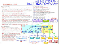
ETSI TISPAN – Resources Admission Control Subsystem (RACS) for Wireline broadband accesses and network peering (See another study note - NASS+RACS)
ITU-T – Resources Admission Control Function (RACF) for Wireless/Wireline broadband accesses, network peering with Explicit identification of Call Admission Control
•OMA (PEEM)
•Parlay (PM-SCS)
•IETF (PDP-PEP Model)


What is Policy?
"Policies" are implemented or executed within a particular context and can be represented at different levels, ranging from business goals to device-specific configuration parameters.
- Policy is a set of rules that governs the authorization, usage and charging for various resources in the network.
- Policies are rules that determine how a service request is handled
- Policies can be static (SLAs) or dynamic (per session)
- Policies can be edited: (1) manually, (2) based on time, (3) based on state
- Policies are interpreted by a rules engine
- Policy control is a highly complex area which presents some major challenges when making decisions about what to deploy and where.

The policies can apply to:
- Policy management is used in the areas of network management where its application is necessitated by the tremendous complexity inherent in the administration and management of networking systems, in QoS management of differentiated networks, in resource and configuration management for network equipment such as routers, and in security management. The same general techniques can be available and applied in the management and delivery of enhanced services. Policy is a broad concept. In a service provider network policies can apply to: - Transport Routing (e.g. OSPF policies)
- Application Routing (e.g. Voice Call Continuity routing)
- Bandwidth allocation
- Firewall traversal
- Billing
- Security
- Identity
- Peering
- 3rd party partners
- Subscribers
- Users
- etc.


PCC (Policy and Charging Control) functionality is comprised by
1) the functions of the Policy and Charging Enforcement Function (PCEF),
2) the Bearer Binding and Event Reporting Function (BBERF),
3) the Policy and Charging Rules Function (PCRF),
4) the Application Function (AF),
5) the Online Charging System (OCS),
6) the Offline Charging System (OFCS) and
7) the Subscription Profile Repository (SPR).

The related elements of policy management in architecture:
1) Policy Enforcement Point (PEP)
- the place in a component that enforces the decision. Policy Enforcement must support and track the addition, modification, or removal of a resource (e.g. application, service enabler, and/or network element) as well as the policy associated with that resource. The major policy enforcement functions:
- Gating: block or admit flows
- Policing: limit the data rate of a flow.
- Marking: set specific bits in the IP, MPLS or Ethernet header of each packet of a flow to ensure that downstream switches and routers give the flow the required QoS treatment
- Metering & Charging: measure the total traffic volume (in bytes) or session duration for charging purposes
2) Policy Decision Point (PDP) - the component making the decision (as like a Rules Engine). Centralized policy management authorizes or denies requests for network resources made by any application or user based on business rules, user profiles, and/or network resource availability. Policy decisions are governed by the subscriber's policy profile as well as any network specific policies in the network the user is currently located.
3) Policy Execution Point - the place in a component actually performing the enforcement and can be merged with Policy Enforcement Point
4) Policy Repository - the component storing the policies
5) Policy Administration Point - for creating, checking policies

What is a Policy framework function (PMF)?
- The decision point or function to control subscriber access to networks and services.
- How policies are reconciled between home and visited network, and where various policies are executed.
- Specific types of policies related to QoS, accounting, mobility (Presence enabled), packet flow optimization (P2P), and access (when at home, always WiFi).
- How policies integrate the network behavior with the applications being invoked.

Involves three major functions in the PMF
- Policy decision function/ engine (like PDP/PCRF)
- Repository of policy rules (like SPR)
- Enforcement point (like PEP/PCEF)

ITU-T RACF:
1) PD-FE – Policy Decision Functional Entity
- Apply network policies to resource management requests from Service Control Functions
- Given an IP address pair and required BW, determine if the given flow can be supported in the network
- Manage resources along the flow path including NAPT Transversal and Gate Control
2) PE-FE – Policy Enforcement Functional Entity
- Provides media path functions such as gate control / Firewall
- NAPT translation and Transversal
- Per flow policing and QoS-marking
- Can provide congestion/capacity information to Service Control
3) TRC-FE – Transport Resource Control Functional Entity
- Connection Admission Control- Monitor network resource utilization and network topology to manage path bandwidth availability (reservation and/or monitor)

IETF PDP-PEP Model:
- In the IETF model, the Policy Enforcement point acts as the policy requestor: Similar to the pull model in ITU and 3GPP standards
- IETF has developed protocols for the PDP-PEP interface: COPS, Diameter
PEP behavior:
- Identifying requests that need an external authorization decision
- Ability to request for external authorization decision
- Enforcing the decision taken in the external authorization function
PDP behavior:
- Receiving a request for taking a decision over an authorization
- Identify relevant policy and take a decision
- Return the decision
- May call delegated resources as part of the evaluation

OMA PEEM:
PEEM specifies ways to convey and enforce policies that can be used to manage resources, processes, and underlying systems. PEEM enabler is driven by the need to reduce management complexity. Via two patterns - proxy pattern or callable usage pattern, PEEM may interact with other resources.
The following is a list of other elements that interact with PEEM:
1) Target Resource Requestor : Target Resource Requestor represents a resource (e.g. application, enabler) that issues a request to a target resource.
2) Target Resource : Target Resource represents the destination resource for a request made by another resource.
3) Delegated Resource : Delegated Resource represents the resource to which PEEM may delegate certain policy actions during the policy processing process.
4) Evaluation Requestor : Evaluation Requestor represents a resource (e.g. application, enabler) that issues a request for policy processing to PEEM.
5) Management Requestor : Management Requestor represents a resource (e.g. application, enabler) that issues a request for policy management to PEEM.
6) Interface to other resources : The interface to other resources is not specified by PEEM, but is used to exchange messages compliant to the interface of the target or delegated enablers or more generally messages compliant to the target or delegated resource interfaces.

The following is a list of PEEM components
1) PEF (Policy Evaluation and Enforcement component)
1.1) PV (PEEM Evaluation).
- is responsible for the policy evaluation portion of the PEEM requirements. This component has the following features:
- identifies the policies associated with the request.,
- evaluates these policies using context information provided by the PEF requestor
- The PV component may use delegation to other resources where appropriate.
- returns, after completing all previous processing, the result of the evaluation to the PEF requestor.
1.2) PF (PEEM Enforcement)
- is responsible for the policy enforcement portion of the PEEM requirements. This component has the following features:
- PF performs the "action" as a consequence of the result that was returned by PV (PEEM Evaluation component),
- The PF component may use delegation to other resources where appropriate
2) PM (Policy Management component)
- provides the functions of describing, creating, updating, deleting, provisioning and viewing of policies
3) Other entities:
- PEF Requestor
- PM Requestor
- Other Resources

The PEEM enabler exposes the following interfaces:
- PEM-1 (PEEM specified callable interface): is used by other resources to make a direct request for policy processing
- PEM-2 (PEEM specified management interface): is used by other resources to make a request for policy management.
- Proxy interface (used for intercepting requests to target resources): is used to exchange messages compliant to the target enablers or more generally messages compliant to combination of the target resource interface and the set of parameters that must be added to requests through that resource’s interface

TISPAN RACS: See another study note - NASS+RACS

3GPP PDF/PCC: See another study note - PCC


Further Information: https://docs.google.com/fileview?id=F.57ac20ef-940b-4181-82f1-3024e6f03a12&hl=en

2009年7月6日

IMS Network Element - RACS+NASS (TISPAN)

IMS Network Element - RACS+NASS (TISPAN) (Study Note)


NASS = Network Attachment Subsystem
CLF = Connectivity session Location and repository Function
NACF = Network Access Configuration Function
UAAF = User Access Authorization Function
PDBF = Profile Data Base Function
CNGCF = CNG Configuration Function

RACS = Resource Admission Control Subsystem
A-RACF= Access-Resource and Admission Control Function
SPDF = Service-based Policy Decision Function

AF = Application Function
CNG = Customer Network Gateway
ARF = Access Relay Function
AMF = Access Management Function
RCEF = Resource Control Emulation Function
BGF = Border Gateway Function
BTF = Basic Transport Functions

NASS Function OV:
- CLF holds a number of records representing active sessions. These records contain information received from the NACF and the UAAF/PDBF, and additional statically configured data. CLF registers the association between network location information received from the NACF and geographical location information.
- NACF is the extension of existing DHCP component and is responsible for the IP address allocation to the UE.
- PDBF contains NASS User authentication data and the NASS User network profile related to the required network access configuration as a Policy Server which is responsible for mapping the subscriber’s services
- UAAF is the extension of existing Radius Server component and performs NASS User authentication, as well as authorization checking, and retrieves authentication data and access authorization information from the NASS User network profile information contained in the PDBF.
- CNGCF is used during initialization and update of the CNG

RACS Function OV:
- A-RACF
performs admission control, Subscriber access profile-based checking and Resource admission control depending on the operator's policy, for the access and aggregation segment.
- SPDF acts as a final Policy Decision Point for Service-Based Policy control (SBP) and makes policy decisions by using service policy rules defined by the network operator, and hides the underlying network topology from applications and from interconnected SPDFs.

Further Information: https://docs.google.com/fileview?id=F.6000c46a-184d-406c-a1d0-1ffa4bf8d82b&hl=en

2009年7月2日

LTE - EPC Overview (Study Note)

LTE - EPC Overview (Study Note)


IASA includes:
- 3GPP Anchor
- SAE Anchor

EPC includes:
- MME
- P-GW:SAE Anchor
- S-GW:3GPP Anchor+UPE

EPC Interface: (Internal)
- S10: MME -- MME
- S11: MME -- S-GW
- S5: S-GW -- P-GW
- S8: (V-P) S-GW – (H-P) P-GW (for Roaming)

EPC Interface: (External)
- S1-C: MME -- eNB
- S1-U: S-GW -- eNB
- S2a: P-GW -- Non-3GPP Trusted IP-Access
- S2b: P-GW -- ePDG of 3GPP WLAN
- S3: MME -- SGSN
- S4: S-GW -- SGSN
- S6a: MMW -- HSS
- S6b: P-GW -- HSS
- S6c: P-GW -- HSS (as an AAA)
- S7: P-GW -- (V-/H-) PCRF
- S13: MME -- EIRS
- S101: MME -- CDMA eAN PCF
- S103: S-GW -- CDMA PDSN
- SGi: P-GW -- P-CSCF
- SGs: MME -- MSC
- S6d: SGSN -- HSS
- S12: eNB -- S-GW -- SGSN (Direct Tunnel)

- S13’: SGSN -- EIR
- S14: UE -- ANDSF (OMA DM)

Mobility management entity (MME): Manages and stores the UE control plane context, generates temporary Id, UE authentication, authorisation of TA/PLMN, mobility management
- The MME manages and stores UE context (for idle-state: UE/user identities, UE mobility state, user security parameters). ŸIt generates temporary identities and allocates them to UEs.
- UE authentication, authorisation of TA/PLMN, mobility management: It checks whether the UE may camp on the TA or on the PLMN. It also authenticates the user.

User plane entity (UPE): Manages and stores UE context, DL UP termination in LTE_IDLE, ciphering, mobility anchor, packet routing and forwarding, initiation of paging
- The UPE terminates, for idle-state UEs, the downlink data path and initiates paging when downlink data arrives for the UE.
- It manages and stores UE contexts, such as parameters of the IP bearer service, or network internal routing information.
- It performs replication of the user traffic in case of interception.

3GPP anchor: Mobility anchor between 2G/3G and LTE ŸThis is a functional entity that anchors the user plane for mobility between the 2G/3G access system and the LTE access system.

SAE anchor: Mobility anchor between 3GPP and non 3GPP (I-WLAN, etc)
- This is a functional entity that anchors the user plane for mobility between 3GPP access systems and non-3GPP access systems.

Further Study: https://docs.google.com/fileview?id=F.faf445b2-5c26-458f-921e-9216357a0b8e