2009年5月14日

LTE - S1+X2 Interfaces (Function + Procedure)

LTE - S1+X2 Interfaces (Function + Procedure) - (Daniel Hu Study Note)


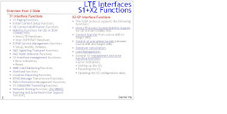
S1 Interface Functions
- S1 Paging function:
- Initial Context Setup Function;
- UE Context Modification Function;
- Mobility Functions for UEs in ECM-CONNECTED:
Ÿ* Intra-LTE Handover;
Ÿ* Inter-3GPP-RAT Handover.
- E-RAB Service Management function: Setup, Modify, Release.
- NAS Signalling Transport function;
- NAS Node Selection Function;
- S1-interface management functions: Error indication; Reset.
- MME Load balancing Function;
- Overload function;
- Location Reporting Function;
- ETWS Message Transmission Function;
- RAN Information Management Function;
- S1 CDMA2000 Tunnelling function.
- Network Sharing Function; (for MBMS)
- Roaming and Area Restriction Support function;

X2 Interface Functions
- The X2AP protocol supports the following functions:
- Intra LTE-Access-System Mobility Support for UE in ECM-CONNECTED:
- Context transfer from source eNB to target eNB;
- Control of user plane tunnels between source eNB and target eNB;
- Handover cancellation.
- Load Management;
- General X2 management and error handling functions:
Ÿ* Error indication;
Ÿ* Setting up the X2;
Ÿ* Resetting the X2;
Ÿ* Updating the X2 configuration data.

LTE - Physical Channel, Transort Channel and Logical Channel Overview

LTE - Physical Channel, Transort Channel and Logical Channel Overview (Daniel Hu Study Note)


Channel List (doc)

The physical DL channels of E-UTRA are:
Physical broadcast channel (PBCH)
- The coded BCH transport block is mapped to four subframes within a 40 ms interval;
- 40 ms timing is blindly detected, i.e. there is no explicit signalling indicating 40 ms timing;
- Each subframe is assumed to be self-decodable, i.e. the BCH can be decoded from a single reception, assuming sufficiently good channel conditions.
Physical control format indicator channel (PCFICH)
- Informs the UE about the number of OFDM symbols used for the PDCCHs;
- Transmitted in every subframe.
Physical downlink control channel (PDCCH)
- Informs the UE about the resource allocation of PCH and DL-SCH, and Hybrid ARQ information related to DL-SCH;
- Carries the uplink scheduling grant.
Physical downlink shared channel (PDSCH)
- Carries the DL-SCH and PCH.
Physical multicast channel (PMCH)

The physical UL channels of E-UTRA are:
Physical uplink control channel (PUCCH)
- Carries Hybrid ARQ ACK/NAKs in response to downlink transmission;
- Carries Scheduling Request (SR);
- Carries CQI reports.
Physical uplink shared channel (PUSCH)
- Carries the UL-SCH.
Physical Hybrid ARQ Indicator Channel (PHICH)
- Carries Hybrid ARQ ACK/NAKs in response to uplink transmissions.
Physical random access channel (PRACH)
- Carries the random access preamble.

The transport DL channels of E-UTRA
Broadcast Channel (BCH) characterised by:
- fixed, pre-defined transport format;
- requirement to be broadcast in the entire coverage area of the cell.
Downlink Shared Channel (DL-SCH) characterised by:
- support for HARQ;
- support for dynamic link adaptation by varying the modulation, coding and transmit power;
- possibility to be broadcast in the entire cell;
- possibility to use beamforming;
- support for both dynamic and semi-static resource allocation;
- support for UE discontinuous reception (DRX) to enable UE power saving;
- support for MBMS transmission.
NOTE: the possibility to use slow power control depends on the physical layer.
Paging Channel (PCH) characterised by:
- support for UE discontinuous reception (DRX) to enable UE power saving (DRX cycle is indicated by the network to the UE);
- requirement to be broadcast in the entire coverage area of the cell;
- mapped to physical resources which can be used dynamically also for traffic/other control channels.
Multicast Channel (MCH) characterised by:
- requirement to be broadcast in the entire coverage area of the cell;
- support for MBSFN combining of MBMS transmission on multiple cells;
- support for semi-static resource allocation e.g. with a time frame of a long cyclic prefix.

The transport UL channels of E-UTRA are:
Uplink Shared Channel (UL-SCH)
characterised by:
- possibility to use beamforming; (likely no impact on specifications)
- support for dynamic link adaptation by varying the transmit power and potentially modulation and coding;
- support for HARQ;
- support for both dynamic and semi-static resource allocation.
NOTE: the possibility to use uplink synchronisation and timing advance depend on the physical layer.
Random Access Channel(s) (RACH) characterised by:
- limited control information;
- collision risk;
NOTE: the possibility to use open loop power control depends on the physical layer solution

The logical control channels of E-UTRA :
Control Channels

Control channels are used for transfer of control plane information only. The control channels offered by MAC are:
Broadcast Control Channel (BCCH)
- A downlink channel for broadcasting system control information.
Paging Control Channel (PCCH)
A downlink channel that transfers paging information and system information change notifications. This channel is used for paging when the network does not know the location cell of the UE.
Common Control Channel (CCCH)
Channel for transmitting control information between UEs and network. This channel is used for UEs having no RRC connection with the network.
Multicast Control Channel (MCCH)
A point-to-multipoint downlink channel used for transmitting MBMS control information from the network to the UE, for one or several MTCHs. This channel is only used by UEs that receive MBMS.
NOTE: is FFS how MBMS scheduling is transmitted by either L2/3 signalling on MCCH or L1 signalling.
Dedicated Control Channel (DCCH)
A point-to-point bi-directional channel that transmits dedicated control information between a UE and the network. Used by UEs having an RRC connection.

The logical traffic channels of E-UTRA :
Traffic Channels

Traffic channels are used for the transfer of user plane information only. The traffic channels offered by MAC are:
Dedicated Traffic Channel (DTCH)
A Dedicated Traffic Channel (DTCH) is a point-to-point channel, dedicated to one UE, for the transfer of user information. A DTCH can exist in both uplink and downlink.
Multicast Traffic Channel (MTCH)

For Further Information:
http://docs.google.com/fileview?id=F.d8bbc727-e881-4859-9bd7-cde24186c3bd

LTE Interfaces – S1 and X2 in U-Plane/C-Plane

LTE Interfaces – S1 and X2 in U-Plane/C-Plane (Daniel Hu Study Note)
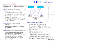


LTE Interfaces S1 and X2 in Network Nodes:

1). The UPE hosts the following functions:
- IP Header Compression and encryption of user data streams;
- Termination of U-plane packets for paging reasons;
- Switching of U-plane for support of UE mobility.

2). The MME hosts the following functions:
- Distribution of paging messages to the eNBs.

3). The eNB host the following functions:
- Functions for Radio Resource Management: Radio Bearer Control, Radio Admission Control, Connection Mobility Control, Dynamic Resource Allocation (scheduling).

On the control plane/user plane separation, we have been instrumental in securing the separation of the MME and the SGW. This will allow for
- independent scaling of the MME based on the number of sessions, and
- independent scaling of the SGW based on the volume of traffic.
- We can also optimize the placement of each of these entities in the network if they are separate and enable one-to-many relationship between MME and serving gateway (S-GW).

S1 Interface (S1-C and S1-U)
The S1 interface is the interface that separate E-UTRAN and EPC. The S1 interface consists of two parts:
- C-plane (Control): S1-C is the interface between eNB and MME function in EPC.
- U-plane (User): S1-U is the interface between eNB and UPE function in EPC.
- The S1 interface shall be specified so that there is a many-to-many relation between aGWs and eNBs.

The protocols over Uu and S1 interfaces are divided into two structures and those interfaces that linked together provide this E-RAB service :
- User plane protocolsThese are the protocols implementing the actual E-RAB service, i.e. carrying user data through the access stratum.
- Control plane protocolsThese are the protocols for controlling the E-RABs and the connection between the UE and the network from different aspects (including requesting the service, controlling different transmission resources, handover etc.). Also a mechanism for transparent transfer of NAS messages is included

S1AP interface protocol structure: (on C-P)
- The radio network (layer) signalling over S1 consists of the S1 Application Part (S1AP over the Transport Network Layer is based on IP transport, comprising SCTP on top of IP.)
- The S1AP protocol consists of mechanisms to handle all procedures between the EPC and E-UTRAN.
- It is also capable of conveying messages transparently between the EPC and the UE without interpretation or processing by the E-UTRAN.

Over the S1 interface the S1AP protocol is, e.g., used to:
*1 Facilitate a set of general E-UTRAN procedures from the EPC such as paging-notification as defined by the notification SAP.
*2 Separate each User Equipment (UE) on the protocol level for mobile specific signalling management as defined by the dedicated SAP.
*3 Transfer of transparent non-access signalling as defined in the dedicated SAP.
*4 Request of various types of E-RABs through the dedicated SAP.
*5 Perform the mobility function.

S1-U interface protocol: (on U-P)
- The S1 user plane interface (S1-U) is defined between the eNB and the S-GW.
- The S1-U interface provides non guaranteed delivery of user plane PDUs between the eNB and the S-GW.
- The transport network layer is built on IP transport and GTP-U is used on top of UDP/IP to carry the user plane PDUs between the eNB and the S-GW.

The S1-U interface supports the tunnelling of end user packets between the eNB and the UPE. The tunnelling protocols support the following functions:
- Indication of the SAE Access Bearer in the target node that the packet belongs to.
- Means to minimize packet losses due to mobility.
- Packet loss detection mechanism
- Error handling mechanism
- MBMS support functions

X2 Interface (X2-C and X2-U)
The X2 interface is the interface between eNBs. The X2 interface consists of two parts:
- C-plane (Control): X2-C is the C-plane interface between eNBs.
- U-plane (User): X2-U is the U-lane interface between eNBs

The X2 interface specifications shall facilitate the following:
- inter-connection of eNBs supplied by different manufacturers;
- support of continuation between eNBs of the E-UTRAN services offered via the S1 interface;
- separation of X2 interface Radio Network functionality and Transport Network functionality to facilitate introduction of future technology.

X2AP interface protocol structure
- The application layer signalling protocol is referred to as X2AP (X2 Application Protocol).
- The transport network layer is built on SCTP on top of IP.
- There shall exist a clear separation between the Radio Network Layer and the Transport Layer. Therefore, the radio network signaling and X2 data streams are separated from the data transport resource and traffic handling

X2-U interface protocol: (on U-P)
- The X2-UP interface protocol stack is identical to the S1-UP protocol stack.
- X2 User plane protocol: Tunnelling protocol GTP-U
- The transport network layer is built on IP transport and GTP-U is used on top of UDP/IP to carry the user plane PDUs.

The X2-U interface supports the tunneling of end user packets between the eNBs. The tunneling protocols support the following functions:
- Indication of the SAE Access Bearer in the target node that the packet belongs to.
- Means to minimize packet losses due to mobility.

Further Information:
2009年5月12日

LTE - Network Architecture and Interfaces

LTE - Study: Network Architecture and Interfaces (Daniel Hu Study Note)


Interface with NEs (doc)
http://docs.google.com/Edit?docid=ddh56dhg_15ffmzjbc4


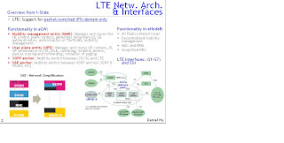
Functionality in eNodeB:
- All Radio-related issues
- Decentralized mobility management
- MAC and RRM
- Simplified RRC

Functionality in aGW:
- Mobility management entity (MME): Manages and stores the UE control plane context, generates temporary Id, UE authentication, authorisation of TA/PLMN, mobility management
- User plane entity (UPE): Manages and stores UE context, DL UP termination in LTE_IDLE, ciphering, mobility anchor, packet routing and forwarding, initiation of paging
- 3GPP anchor: Mobility anchor between 2G/3G and LTE
- SAE anchor: Mobility anchor between 3GPP and non 3GPP (I-WLAN, etc)

Further Information:
http://docs.google.com/fileview?id=F.fb95caf8-cbac-48aa-bd8a-7543cb5d1797